

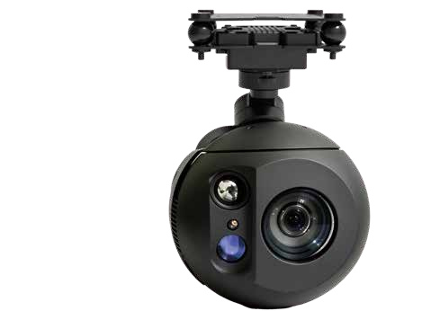
The GC30 Dual Sensor Gimbal Camera is listed as a three-axis assembly, so a mounting discussion should consider moving geometry as well as a parked outline. Its available brochure references do not establish the complete dimensions or a verified motion envelope for a particular aircraft. Leave those requirements with the configuration-specific mechanical review. For civil UAV inspection equipment, identify the camera version, nearby structure and selected cables before accepting a clearance conclusion. A product photograph can show the assembly, but it cannot prove that every position needed by the project fits inside a proposed support.
Distinguish a parked outline from moving space
A product image usually shows one position of a camera assembly. That position may be convenient for photography rather than representative of the space required around the moving unit. Even a dimensioned static drawing answers only the question its dimensions address. It should not silently become proof of the room needed for an articulated head.
The first review document can therefore contain two separate entries: the assembly in its identified reference position, and the movement-related information needed for the proposed arrangement. If the second entry is unavailable, mark it as pending. The team can still compare equipment identities and reserve preliminary space while acknowledging that the mechanical assessment remains incomplete.
A simple sketch should name its purpose. “Concept layout for supplier discussion” is appropriate when surrounding geometry has not been verified. Avoid labelling an approximate shaded area as the GC30 motion envelope. That label would suggest that the manufacturer established boundaries the available material does not provide. The distinction matters when a sketch passes from purchasing to a designer who did not attend the original conversation.
Three axes need a shared geometric reference
Three-axis language describes three rotational freedoms in a gimbal arrangement. General camera discussions often describe pan, tilt and roll, but the exact coordinate definitions and documented limits must come from the selected assembly. A label in an introductory diagram is not a replacement for those definitions.
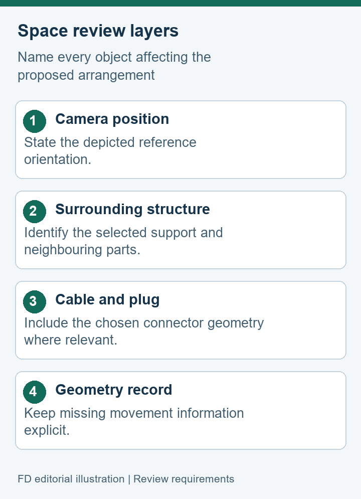
Ask the mechanical reviewer to identify the reference orientation used by the drawing. The camera head, mounting surface and aircraft reference should be distinguishable. This makes a discussion of “left,” “down” or “side clearance” less ambiguous. Those everyday words are convenient during a meeting but can become unreliable when two drawings show the assembly from different directions.
The GC30 brochure's three-axis description does not provide a basis here for quoting unrestricted rotation, a specific travel angle or a stabilized pointing accuracy. Keep those separate from the basic assembly identity. If a project needs a documented movement range, the camera supplier should identify the version and supporting record, and the platform reviewer should assess it against the actual surrounding parts.
- Reference geometry
- Which camera position and mounting plane are shown?
- Movement information
- Which version-specific record defines the required clearance?
Surrounding parts belong in the same review
The available room is determined by more than the camera. A support, an aircraft underside, a nearby housing and any project attachment can form the relevant boundaries. Show the selected surrounding parts on the review drawing, with their own names and revisions. Otherwise, a camera-only conclusion may be misread as a complete assessment of the installed arrangement.
Consider a civil inspection team comparing two proposed supports. One drawing may leave the camera visible from several directions; another may place a protective structure close to it. Neither appearance establishes suitability. The useful comparison is which drawings contain the relevant dimensions and who has assessed the complete proposed geometry. The review should identify the supported arrangement rather than awarding a general “fits” label to the model.
Changes to neighbouring parts deserve the same attention as changes to the camera. A replacement cable connector or a revised support plate can affect space while leaving the GC30 model name unchanged. Keep the reviewed parts list connected to the clearance note so that a later substitution does not inherit a conclusion reached for a different assembly.
Cable space is part of the physical arrangement
The brochure lists HDMI and IP video alongside several control-interface families. Those references do not identify every connector body or cable in an offered package. A chosen cable should have its own part identity and documented dimensions where they matter to the layout. Do not infer a selected cable from a generic interface label.
A mechanical review can distinguish the plug's occupied space, the cable route proposed by the responsible installer and the access needed for service. These are documentation categories, not a wiring procedure. The camera's revision-specific instructions should govern the actual installation. A concept diagram may illustrate the categories without claiming an approved cable route.
Record whether the drawing includes the connected cable or only the camera body. This small note can prevent a costly misunderstanding. When the cable has not been selected, the review may need to retain a provisional space requirement and a named unresolved item. A neat camera outline is not evidence that an unspecified connector will fit behind it.
Give each missing dimension a named owner
A missing dimension is easier to resolve when its source is clear. Camera-side geometry comes from the relevant camera documentation. Bracket dimensions come from the support designer. Aircraft restrictions come from the platform documentation and its responsible reviewer. Combining these into a vague request for “full compatibility” makes it harder to see what is actually absent.
- Identify the assembly. Name the offered GC30 version and the documents currently available for it.
- Name the surrounding parts. Include the proposed support and any selected project attachments in the drawing index.
- Locate the evidence gap. State whether the missing information concerns the camera, a cable, the bracket or the aircraft.
- Record the review owner. Give the relevant supplier or designer a precise question tied to that document.
This sequence is a way to organize information, not a clearance test. It does not require a team to invent dimensions to complete the page. “Pending camera-side drawing revision” is a useful status when it is accurate. It allows the next discussion to focus on the missing record while keeping the rest of the equipment comparison intelligible.
Preserve the response with the document it clarifies. An email describing a different assembly should not become an informal substitute for a revised drawing of the selected one.
Describe clearance evidence without overstating it
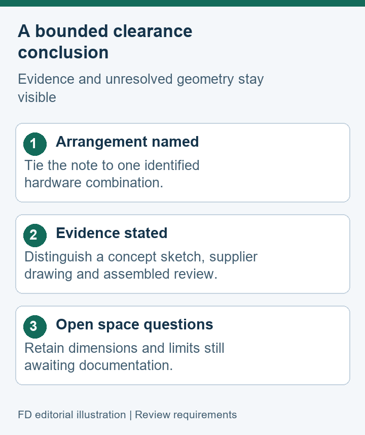
A clearance record should say what was reviewed and what the evidence supports. A rendered concept, a supplier drawing and an assessment of the assembled equipment are different records. Label them accordingly. Their value does not depend on making each one sound like a completed physical test.
| Evidence type | Useful meaning | Limit to retain |
|---|---|---|
| Concept sketch | Shows the proposed equipment relationship | Approximate geometry remains preliminary |
| Supplier drawing | Names the camera assembly and stated dimensions | Other parts still need their own records |
| Arrangement review | Addresses the identified assembled combination | The conclusion belongs to those selected parts |
For example, a drawing review may establish that two documented outlines do not overlap in the depicted reference position. That is narrower than establishing clearance through the required movement. If a responsible reviewer has assessed additional geometry, identify the record and the exact arrangement. Do not turn an unlabelled photograph into proof of a motion range.
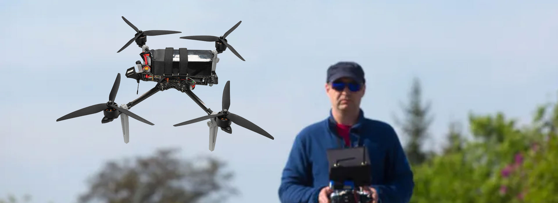
Any retained photographs should show identifiable equipment rather than stand alone as a universal compatibility claim. A photo can document the parts present in one arrangement. It may omit a hidden interference, a different cable or a dimension that the reviewer needs. Link its meaning to the documented assembly and the limited conclusion rather than to the product name alone.
Carry the arrangement into the equipment handover
The handover should connect the chosen hardware with the review documents. A future technician needs to know whether a replacement support or cable matches the parts that were considered. A model name and a product photograph are rarely enough to answer that question, especially if several offers use similar-looking assemblies.
Keep an arrangement identifier, the relevant document revisions and a list of selected attachments together. The identifier can be project-specific; it does not need to imply a manufacturer configuration code. Its purpose is to make the equipment record findable and distinguish it from another proposal. If a component changes, the team can then identify which mechanical conclusion may need attention.
The GC30 Dual Sensor Gimbal Camera reference page identifies the model's listed three-axis assembly and imaging roles. Use that identity to request the appropriate mechanical material. Keep any platform-clearance conclusion with the responsible review of the selected physical arrangement.
GC30 gimbal clearance questions
Does “three-axis” tell me how much space to reserve?
It identifies the assembly's rotational freedoms, not a complete dimensional or movement envelope. The exact version and proposed installation need documented geometry. No specific GC30 travel limits are established in this article.
Can a parked product photograph settle a movement-clearance question?
It shows one visible arrangement. A movement-related conclusion needs evidence addressing the relevant geometry and surrounding parts. The photograph can help identify those parts without proving every required position.
Should a replacement cable appear in the mechanical record?
Yes, when its connector or route affects the reviewed arrangement. Identify the selected part and assess the change through the responsible review. A shared interface name does not establish identical physical dimensions.
What if no complete GC30 dimensional record has been supplied?
Retain a preliminary layout and name the missing documentation. Do not borrow dimensions from another camera or convert a scaled product image into a manufacturing reference. The supplier should identify the correct assembly information.



 Tel: +86-13959965075
 Email: info@fpvdroneskit.com
 MP/WhatsApp: +86-13959965075
 Manufacturer Address:Quanzhou Valley Nanan Science and Technology Innovation Center, No. 89 Shijing Avenue, Shijing Town, Nanan City, Fujian Province