

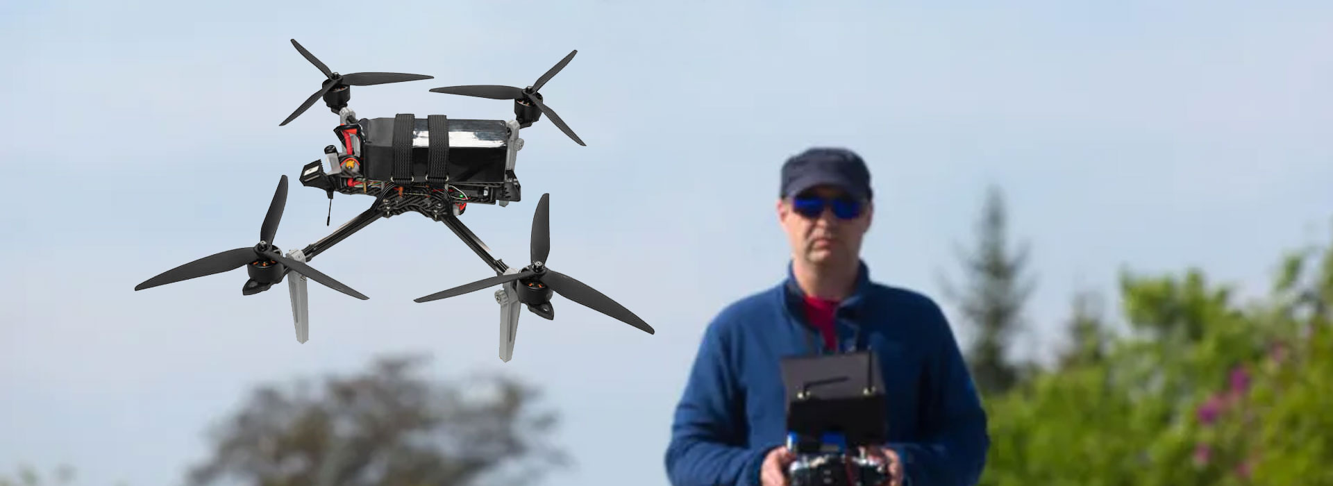
GC10 integration is easier to describe when picture delivery, camera commands and gimbal movement have separate records. The manual names micro HDMI and IP video, plus PWM, S.Bus, serial TTL and network control references. Those labels identify interface families; they do not assign every desired action to every connector. For an FPV or civil UAV project, start with the result each connection must provide, then obtain its revision-specific interface information. A live picture shows that a viewing path is working in the demonstrated arrangement. It does not establish that the same arrangement can change focus or control the gimbal.
Begin with a visible result or a requested action
An integration discussion often starts with a broad sentence such as “connect the camera to the controller.” That wording hides several jobs. One person may mean viewing the picture, another may mean selecting a camera function, and a third may mean controlling the orientation of the assembly. Giving each job a name helps the supplier answer the actual requirement.
Use ordinary descriptions first. “The review screen receives a visible picture” is a viewing requirement. “The application requests a focus change” is an imaging-control requirement. “The selected control input moves the gimbal” is a motion-control requirement. These examples are project questions, not a claim that a particular GC10 configuration performs all three through the same path.
The separation is valuable even when several functions share a physical connection. The team still needs to know which software interprets each request, which component returns a status and where the result appears. A cable name alone cannot describe those responsibilities. Conversely, keeping the roles separate does not imply that a system must use three independent cables.
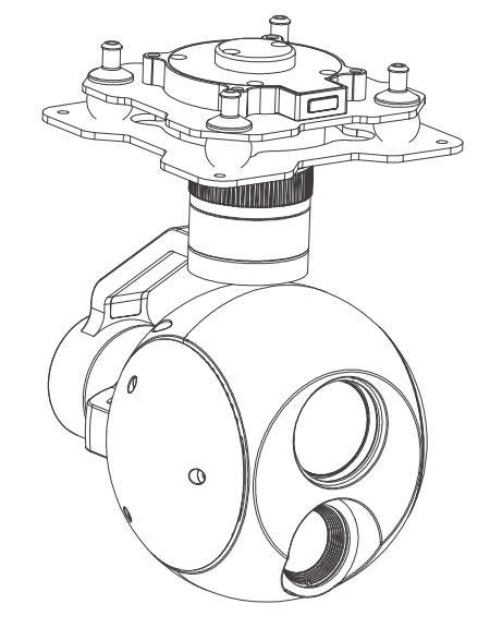
Picture delivery has its own destination
The GC10 source lists both micro HDMI and IP video outputs. This article does not repeat their resolution table; the question here is where the selected output is supposed to go. A receiving screen, an application and a recording device are different destinations, even when they are used together in one project.
Describe the proposed viewing destination by its actual identity and selected input. Add the supplier's statement about the output used in that arrangement. If a demonstration has intermediate equipment, include it in the description. The camera-side interface and the screen-side input may otherwise look deceptively complete while a necessary conversion or software component remains unnamed.
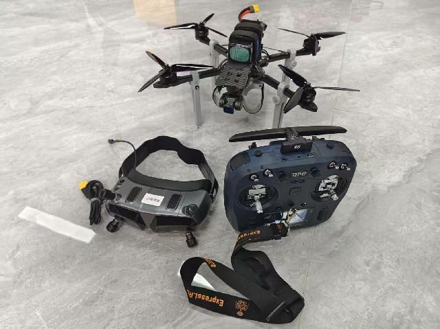
A photograph of a controller displaying an image can identify a demonstration, provided its equipment and configuration are known. It does not explain every connection behind the screen. For a reproducible record, the demonstration should say which source, output and receiving arrangement were used. This preserves a useful viewing claim without extending it into an unsupported compatibility list.
What is received, and which destination displays it?
Which documented command requests the camera function?
Which supported control path addresses the gimbal?
Camera commands describe imaging actions
The manual identifies visible-camera focus modes and optical zoom. To use an imaging function from an application, the integrator needs the relevant control information for the offered camera revision. A feature appearing in the camera specification does not automatically provide a button in every ground-station application.
Record the requested action and the interface document that defines it. A useful entry might identify a focus request, its supported camera-side method and the application responsible for making it available. Leave an unsupported or undocumented action unresolved. This is preferable to assigning a generic protocol name and assuming the missing command will exist.
The application may also need a way to distinguish a request from a completed action. The exact response and status behavior belong in the protocol information or supplier demonstration. Do not invent them from a familiar interface family. For example, the presence of a serial interface does not say which messages a camera accepts or whether the proposed application understands those messages.
Identify the origin of any success notice in the review evidence. A notice from an application can describe its own request handling, while a camera-side result has a different origin. The supplier's documented behavior should explain that distinction. Keeping the notice attached to its producing component prevents a convenient screen message from becoming an unsupported statement about completed hardware action.
Gimbal commands describe assembly movement
The GC10 is described as a three-axis gimbal assembly. Motion control concerns that assembly rather than the image delivered to a screen. A displayed picture may remain available even when a requested movement has not been connected to the intended control input. The review should therefore give motion its own stated result and supporting evidence.
Describe the offered control arrangement using the supplier's documentation. Identify the source of the request and the component responsible for translating it, if translation is required. This keeps the description understandable without providing unverified wiring or control instructions. Exact limits, assignments and operating behavior should remain tied to the actual revision.
General PX4 documentation treats camera integration and gimbal configuration as related but distinct subjects. That is useful background for a role map. It does not establish that GC10 is a native MAVLink device or that a particular PX4 arrangement has been tested with it. Keep a project-specific compatibility statement separate from the general architecture vocabulary.
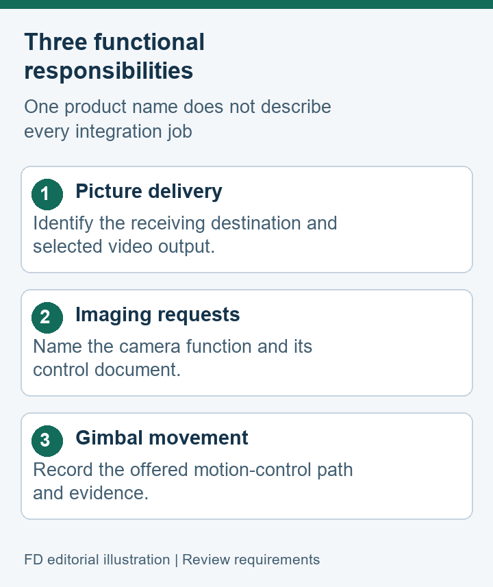
Connector names need protocol documentation
A connector identifies a physical meeting point. An interface family gives additional context, but an application still needs the actual information exchanged through that interface. This is why a list containing PWM, S.Bus, serial TTL, TCP and UDP should lead to a document request rather than a universal control claim.
Keep three questions distinct: which hardware is present, which communication method is documented, and which functions the offered arrangement exposes. A supplier response can then address the missing layer. If the project requires a particular software integration, identify that application and ask for evidence from its stated version instead of relying on an interface label.
The source's network-control reference also needs a functional description. A network carrying video does not, by that fact alone, define the commands used for camera or gimbal control. The connection may support several roles in the offered system, but the supplier should identify those roles explicitly. This avoids silently borrowing behavior from another camera with a similar specification list.
| Layer | Information to identify | Evidence location |
|---|---|---|
| Physical | Selected connector and cable identity | Hardware documentation |
| Communication | Documented interface and message definitions | Revision-specific protocol material |
| Function | Requested action and demonstrated result | Offered-system software record |
Prepare a responsibility map for the offered system
A role map can fit on one page. Give each required result a row, name the originating component, and identify the destination or controlled object. Include any adapter or software bridge named by the supplier. Mark an unknown component plainly rather than filling the gap with a plausible diagram.
For a hypothetical project, the map might contain a viewing row owned by the display integrator, an imaging-control row owned by the application developer, and a motion row owned by the control-system supplier. The owners need not be separate companies. Naming the jobs is what matters: it lets a combined supplier answer each responsibility without hiding one inside another.
Use the map during a sample review. If only the picture path has been demonstrated, the viewing row can retain that evidence while the two control rows remain pending. This is more informative than marking the whole system either “working” or “not working.” It also prevents a future reviewer from treating one successful demonstration as proof of every requested action.
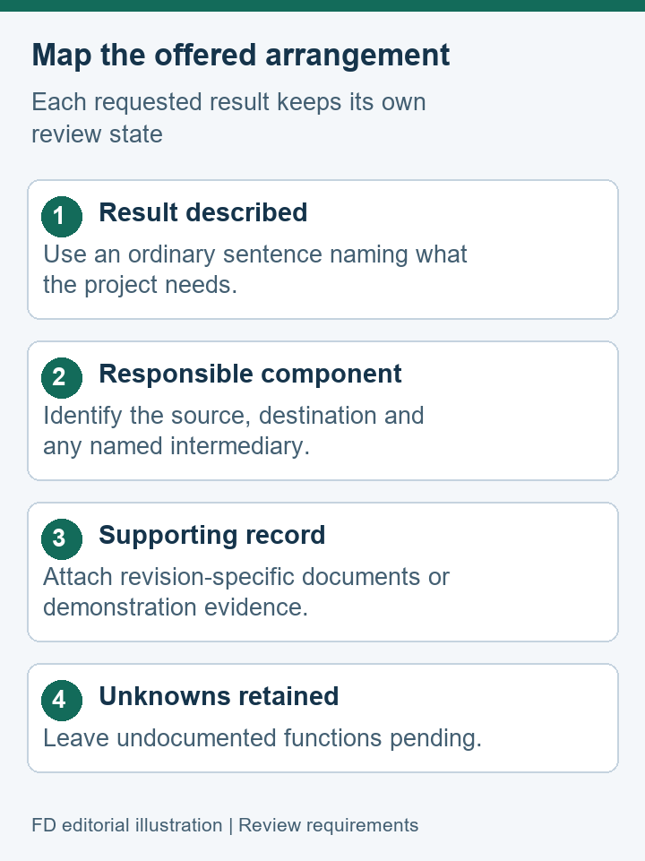
Keep demonstrations attached to the correct claim
When a supplier supplies a demonstration, describe its purpose and equipment. A screen photograph supports a visible arrangement; a documented command exchange may support an imaging function; an identified motion demonstration addresses a different result. Each record should carry the model revision and relevant software identity.
A comparison between offers becomes clearer when all three jobs have the same headings. The information inside those headings can differ substantially. One offer may provide a documented bridge, while another may require application work. The point is to expose that difference before the team assumes the camera specification also describes the delivered software.
The GC10 Dual Sensor Gimbal Camera model page provides the listed interface families and imaging references. Use it to identify the hardware under discussion. For the offered complete arrangement, retain a separate map of viewing, camera-command and gimbal-control responsibilities.
GC10 interface role questions
Does receiving a GC10 picture prove application control is available?
It establishes the demonstrated viewing result. Camera actions and gimbal movement require their own documented control paths. A project should retain those as separate review items even if the supplier proposes a shared connection.
What can a PWM or serial entry tell an application developer?
It identifies an interface family to investigate. The developer still needs the supported function definitions and revision-specific information. A familiar transport name cannot supply an undocumented camera command.
Must picture, imaging actions and motion use separate cables?
This article does not specify the cable arrangement. The offered system may combine responsibilities or separate them. The useful requirement is that each role, intermediary and relevant document is identified clearly.
Where should a claim of QGroundControl compatibility be recorded?
Keep it with evidence for the named camera revision, application build and complete arrangement. General protocol documentation explains possible architectures; it does not certify the GC10 combination being offered.

 Tel: +86-13959965075
 Email: info@fpvdroneskit.com
 MP/WhatsApp: +86-13959965075
 Manufacturer Address:Quanzhou Valley Nanan Science and Technology Innovation Center, No. 89 Shijing Avenue, Shijing Town, Nanan City, Fujian Province