


Thermal image basis
The manufacturer lists 640 ×512 pixels, 12 µm pixel spacing and an 8–14 µm wavelength range. These describe the detector class, rather than a recognition distance or a guarantee of temperature accuracy.
| Price | On request |
|---|---|
| Model | DIP640H25 |
| Thermal detector | 640 ×512; 12 µm; LWIR8–14 µm |
|---|
| Storage / file formats | Local TF described |
|---|
| Stabilization | Three-axis |
|---|---|
| Power input | 12–26.2 V DC; Dynamic6 W |
| Weight | 370 ±10 g excluding dampers |
| Video output | RTSP network stream |
|---|---|
| Control interfaces | Serial / network |
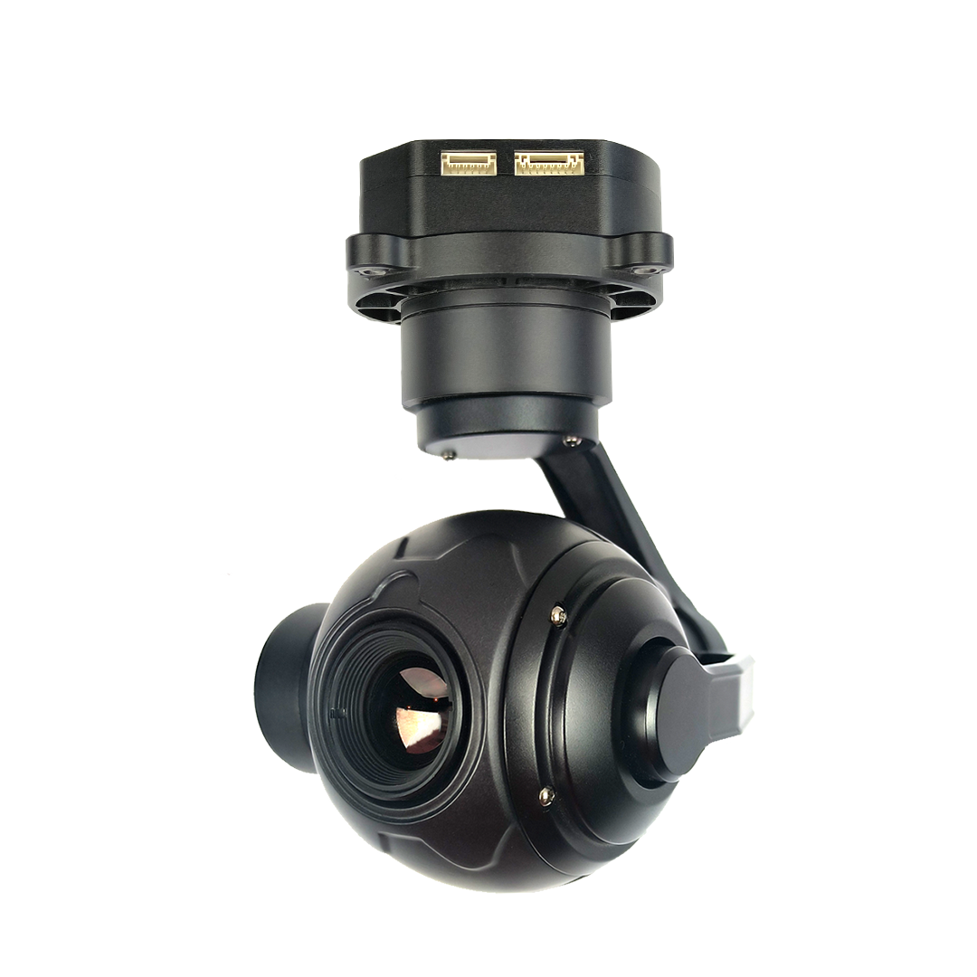
DIP640H25 is a three-axis thermal gimbal camera for civil UAV imaging. It uses a 640 ×512 long-wave infrared detector and a nominal 25 mm lens, with RTSP network output. This is a thermal-only configuration: select it for a thermal viewing task, and choose a dual sensor camera instead when a built-in visible channel is also required.
| Result | What the customer uses | What must be specified |
|---|---|---|
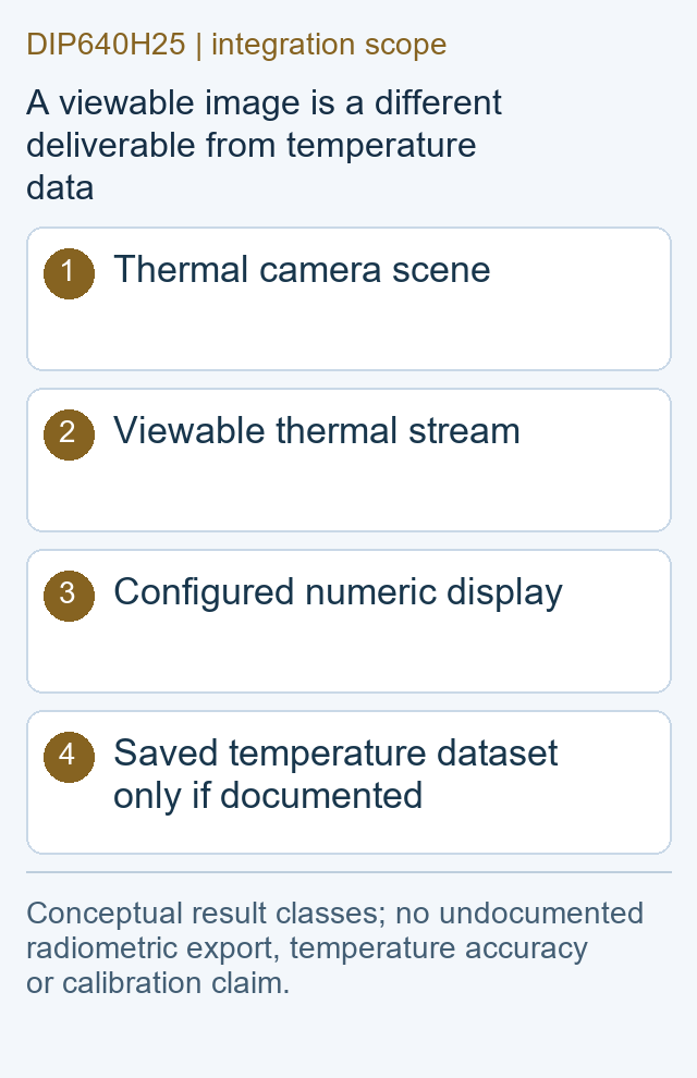
| Viewable thermal video | A live or recorded scene rendered as an image | Receiving software, stream mode and recording behavior |
| Displayed temperature | Numeric values shown for a selected scene region | Delivered measurement functions and their stated conditions |
| Temperature data file | Data for later analysis beyond a colored image | Whether such export exists, its format and software rights |
A colored thermal recording and a temperature dataset are different outputs. A palette can help the operator see contrast, but the palette itself does not establish a numeric temperature. The maker describes point and area functions; the actual supplied measurement configuration, accuracy documentation and saved-data capability need their own delivery description.
The manufacturer lists 640 ×512 pixels, 12 µm pixel spacing and an 8–14 µm wavelength range. These describe the detector class, rather than a recognition distance or a guarantee of temperature accuracy.
The source names a nominal 25 mm lens but puts multiple field-of-view pairs in the same row. A single verified angle is therefore withheld here; the offered lens configuration needs a corrected specification.
For a roof survey or equipment observation, determine whether the required scene fits the actual lens view and whether the saved image contains sufficient detail. Do that with the offered variant and original output. Selecting an angle from an inconsistent table would make coverage planning look precise without establishing the camera's real optical configuration.
The same distinction applies to sensitivity and measurement. Thermal contrast can reveal a difference worth investigating, while an actual temperature result depends on the measurement method and scene conditions. Keep reflections, materials and background context with the inspection record instead of treating a bright-looking feature as a confirmed fault.
RTSP is named for the network picture. Select a receiver and display able to use the supplied stream, and decide where recording takes place. The product description also names TF storage, but the required exported files and channel presentation should be documented from a representative unit.
Serial and network control are listed separately from video. Keep the command specification with the supplied firmware, cable and configuration. Manufacturer ground software is described for camera and gimbal operation; its presence in the source is not proof of FD-developed software, a universal flight-controller interface or compatibility with every UAV ground station.
Three-axis stabilization provides a pointing mechanism, but the product page is not a flight-test record for the customer's aircraft. Compare unedited output from the intended mount and working conditions before promising image stability. The thermal-only camera also needs a separate way to preserve visible scene context if the report requires both kinds of evidence.
No visible channel is established for this model. A dual sensor product is the appropriate category when built-in visible and thermal views are both required.
A rendered image does not establish saved per-pixel temperature data. State the export format and analysis software when those results are required.
Use the corrected specification for the offered lens. The public page contains multiple pairs under one lens label, so this page does not select a pair by assumption.
Identify the exact optical variant, measurement scope, software rights, output files, mounting accessories and interface document. These define a usable package without inventing missing specifications.
Original model reference: TOPOTEK DIP640H25. Detector and interface facts follow the manufacturer's page. The inconsistent lens-angle row and undocumented measurement/file conditions are kept separate from confirmed specifications. Manufacturer specification source.
| Thermal Imager | 640 ×512; 12 µm; LWIR8–14 µm |
|---|---|
| Stabilization | Three-axis Not proof of customer-UAV field image stability. |
| Video Output | RTSP network stream Delivered stream dimensions and frame rate require revision documentation. |
| Storage | Local TF described Does not establish saved radiometric per-pixel files. |
| Control | Serial / network |
| Weight | 370 ±10 g excluding dampers |
| Voltage | 12–26.2 V DC |
| Power | Dynamic6 W Not guaranteed peak supply requirement. |
Manufacturer-listed values. Supplied options and installed weight belong in the quotation.
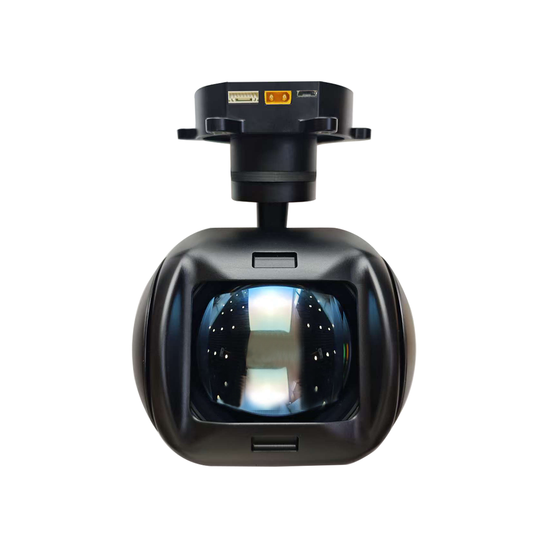
Select DIPG12 thermal UAV imaging with 1280×1024 resolution, an 85 mm lens, RTSP video and TF storage. Request the right mounting package....
Explore DIP640H25 thermal-only UAV imaging with a 640 ×512 detector, RTSP video and separate viewing, temperature-display and saved-data requirements....

 Tel: +86-13959965075
 Email: info@fpvdroneskit.com
 MP/WhatsApp: +86-13959965075
 Manufacturer Address:Quanzhou Valley Nanan Science and Technology Innovation Center, No. 89 Shijing Avenue, Shijing Town, Nanan City, Fujian Province