

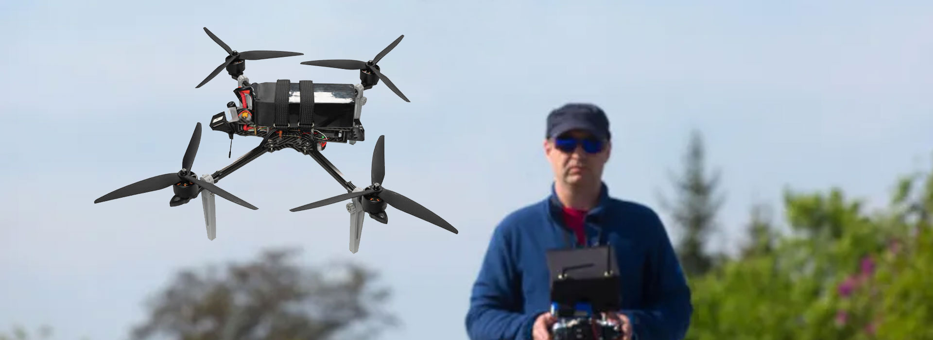
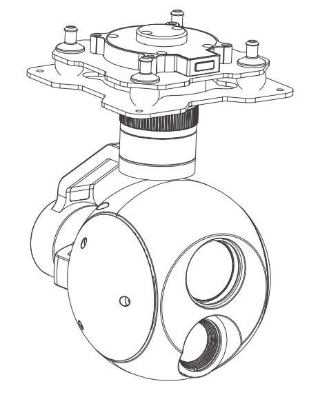
A GC10 Dual Sensor Gimbal Camera mounting review needs more than its overall dimensions. The supplied manual lists a 121.5 × 96 × 158.1 mm assembly and a 730 g quick-release version, including that mechanism. Those references describe a particular camera assembly; they do not define the bracket holes, aircraft clearance or complete installed payload. For a civil UAV or FPV inspection project, give the bracket designer the drawing revision, mounting interface and equipment boundary together. This lets the team compare the proposed parts without treating a product photograph as a dimensioned installation drawing.
Overall size is a starting envelope
Three dimensions help a designer reserve space for an object. They are especially useful at the first layout discussion, when the camera, aircraft underside and proposed support are being considered together. However, the numbers alone do not say where the reference planes lie. A height measured to the top of a release fitting is different from a camera-body height measured beneath it. The drawing should make that difference visible.
Put the supplied dimension reference beside a dated drawing of the proposed bracket. Describe which end of the assembly is nearest the attachment surface and which parts remain below it. If the arrangement is still being selected, identify it as a preliminary layout. This prevents a convenient sketch from becoming an undocumented manufacturing instruction.
The GC10 manual also describes a three-axis gimbal and integrated vibration damping. An overall size entry should not be read as a complete swept-space diagram for those moving parts. The static drawing and the motion-clearance document serve different purposes. A bracket that appears to surround the parked camera neatly still needs a separate assessment of the assembled geometry.
Keep the quick-release mass in its proper scope
The listed 730 g belongs to the quick-release version and includes its release mechanism. That wording is useful because it identifies part of the assembly boundary. It does not state the mass of a complete aircraft installation containing a custom support, fasteners, external cables and other equipment. Those items need their own entries rather than disappearing into a generic “camera weight” row.
A project may already have an approved payload allowance. The person responsible for that allowance should receive a list of actual selected parts, with measured or supplier-documented masses where available. This article cannot establish that allowance or certify an airframe. Its purpose is to make the camera contribution distinguishable from the rest of the proposed assembly.
Consider a drawing marked “GC10” and an offer marked “GC10 with quick release.” They may refer to the same supplied version, but the name alone does not establish that. The designer should resolve the wording before treating either document as the equipment definition. If a release mechanism is removed or replaced in a proposed design, record the changed boundary and obtain the relevant component information.
Read the mounting interface as a separate object
The mounting interface is where the camera assembly and its support meet. It needs more information than the outer dimensions: the relevant attachment pattern, reference surfaces and revision must be identified in the appropriate drawing. If those details are absent from the material being reviewed, the designer has an information gap, not permission to infer a pattern from a small illustration.
A technical line drawing can help locate an interface and distinguish the camera head from its support. It is not necessarily a manufacturing drawing. A scaled printout is also an uncertain basis for measuring a hole position, because page fitting and image export can change its apparent size. Use labelled dimensions and revision-specific documentation for the mechanical decisions.
The quick-release wording deserves particular attention here. Ask whether the proposed support engages the documented release assembly or attaches through a different supplied component. The answer changes what the bracket drawing should depict. It may also change which instructions, retention details and inspection responsibilities belong in the equipment packet. Do not assume that every GC10 offer includes every visible fitting.
Make room for connectors and surrounding parts
A camera outline occupies only part of the available space. A connected cable, its plug and a nearby structural part may occupy more. The actual assembly review should show the proposed connectors and their direction, without inventing a wiring arrangement. A connector photograph is useful for identification, while a cable drawing is better evidence for the selected cable's dimensions.
Separate the connector-body space from the space needed to handle or service it. A plug that fits in an illustration may still be awkward to reach in the proposed arrangement. The responsible installer should assess that access using the exact components and approved installation information. This is a mechanical documentation question, not a suggestion to alter the camera connector.
Nearby items deserve names on the layout. “Support plate,” “airframe surface” and “selected cable” are more informative than an unlabeled shaded region. If the aircraft drawing is unavailable, state that the camera-only layout has not established the surrounding clearance. That qualification keeps a preliminary product comparison from being mistaken for a completed platform integration.
A compact drawing packet for the bracket designer
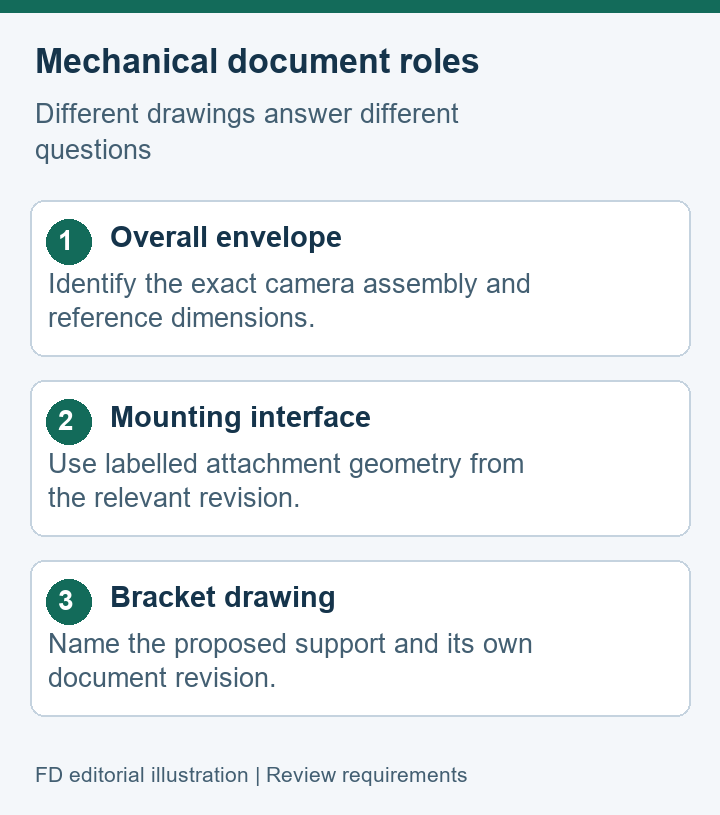
A useful packet can be small if its documents have clear jobs. Start with the exact offered assembly identity, then add the corresponding dimensional information and the proposed bracket drawing. Keep a parts list beside them. The designer should be able to find the source of a dimension and understand whether an attachment is included, selected separately or still undecided.
| Record | What it should identify | What it does not settle alone |
|---|---|---|
| GC10 assembly reference | Offered version and quick-release scope | The complete installed payload |
| Interface drawing | Attachment surfaces and labelled geometry | Airframe approval |
| Proposed bracket drawing | Selected support and revision | Camera motion limits |
| Parts schedule | Camera, support and selected attachments | Unlisted accessories |
The rows are a documentation example, not a statement that these drawings are included with every order. A supplier can identify which records are available for the offered version. The project team can then assign the remaining work rather than asking one brochure page to serve every design purpose.
Put an owner next to each unresolved entry. A missing aircraft drawing belongs with the platform designer; a missing camera-interface revision belongs with the camera supplier. Naming those owners reduces repeated requests and makes a later change easier to assess.
Resolve mismatched assembly descriptions
Different documents can describe different boundaries without either being obviously wrong. A product page may show the complete camera, while a packing list names a camera and a separate fitting. A bracket illustration may have been prepared for another assembly revision. The practical task is to reconcile those identities before relying on the geometry.
Keep the original documents when a discrepancy appears. Add a short comparison note containing the document names, revision labels and conflicting description. This gives the supplier a specific question to answer. “Which assembly does this height include?” is easier to resolve than a broad request to verify every specification again.
A revised drawing should carry its own date or revision identifier. Do not simply replace the older file while leaving an unchanged review note. The note should point to the document actually accepted. If the proposed bracket also changes, describe which earlier drawing is superseded and which elements still require review.
Write a decision that names the reviewed parts
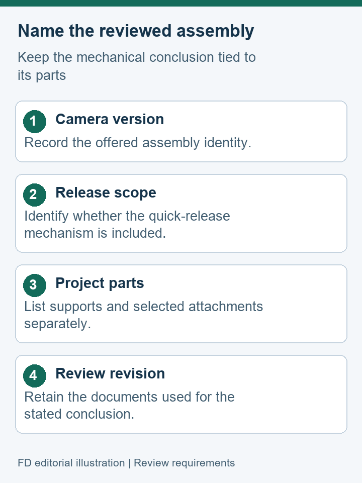
The result of a mounting review should identify what was considered. A statement such as “camera size checked” is too broad to explain whether the quick release, external cables and proposed support were included. A stronger record names the GC10 version, source drawing and bracket revision, then states the limited conclusion reached by the responsible reviewer.
For example, a project may accept a preliminary camera envelope while leaving the mounting interface unresolved. That is a useful decision when described accurately. It allows the layout work to continue without presenting the bracket as ready for manufacture or the aircraft as cleared for use. Another review may identify a documented support assembly but still require a platform assessment.
Use the GC10 Dual Sensor Gimbal Camera product reference to identify the model and listed assembly facts. Bring the configuration-specific drawing information into the actual bracket review. The product page gives a starting identity; the named engineering documents should carry the mechanical conclusion.
GC10 mounting drawing questions
Can the listed overall dimensions define a mounting-hole pattern?
No. The external envelope and the attachment geometry answer different questions. A mounting pattern needs its own labelled interface information. Measuring an illustration or assuming a common pattern would add a detail the stated dimensions do not provide.
Why does the quick-release wording matter to the weight entry?
It identifies the version represented by the 730 g brochure reference and says the mechanism is included in that assembly. It does not account for every project attachment. Keep additional supports and selected cables in separate rows.
Does the product drawing establish compatibility with a particular UAV?
It identifies camera-side geometry. Platform suitability still depends on the selected support, aircraft constraints and documented installation assessment. No airframe compatibility result follows merely from fitting a camera outline into an aircraft sketch.
What should change when the offered assembly revision changes?
Update the equipment identity and check the affected drawing references. Record which conclusion relied on the earlier revision. A clear revision note is preferable to retaining a generic approval that no longer names the supplied parts.

 Tel: +86-13959965075
 Email: info@fpvdroneskit.com
 MP/WhatsApp: +86-13959965075
 Manufacturer Address:Quanzhou Valley Nanan Science and Technology Innovation Center, No. 89 Shijing Avenue, Shijing Town, Nanan City, Fujian Province