Author:Military Drone Manufacturer TIME:2026-11-04
Budget the Reebot UniPod MT11 as the assembly you will actually install, rather than as a 405 g camera in isolation. Reebot lists 405 ± 5 g without the quick-release anti-vibration board and 533.5 ± 5 g with the quick-release board and interface dock. The nominal difference is 128.5 g before any aircraft-specific bracket, extra cable or power hardware. Use the heavier figure when that mounting package is required, then add only the parts outside its stated scope. This approach helps identify a realistic UAV fit without claiming that a bare-camera weight proves endurance, mechanical compatibility or adequate vibration isolation.
Without the quick-release anti-vibration board. Do not assume the aircraft needs no additional mounting or interface parts.
The listed package contains the interface dock and the anti-vibration quick-release board. Aircraft-specific additions remain separate.
Use the following worksheet with your own component values. It deliberately separates the manufacturer-listed MT11 assembly from invented example accessories. None of the extra masses below is a Reebot specification or an indication of what FD includes as standard. The purpose is to reveal the items that a bare-camera figure leaves out.
| Installed item | Illustrative mass | Basis |
|---|---|---|
| MT11 with board and dock | 533.5 g nominal | Manufacturer value for this stated assembly |
| Aircraft-specific adapter bracket | 35 g | Assumed example; replace with the actual part |
| Additional aircraft-side cables | 22 g | Assumed example, excluding anything already included above |
| Separate power hardware | 18 g | Assumed example where the installation requires it |
| Illustrative installed total | 608.5 g nominal | 533.5 + 35 + 22 + 18 |
| Using the listed assembly's upper weight tolerance | 613.5 g | Add 5 g; unknown accessory tolerances are still excluded |
If a hypothetical design allocates 650 g to this complete assembly, the last row leaves only 36.5 g before other uncertainty or engineering allowances. That remainder is arithmetic, not a recommended safety margin or permission to fly. The aircraft's own limits, loading conditions and approval process still decide whether the installation is acceptable.
Most importantly, avoid double counting. If a cable is already included in a supplied assembly, do not add it again as an aircraft-side accessory. If it is absent from the package, leaving its weight blank does not make it disappear. The usefulness of the calculation depends on its component scope.
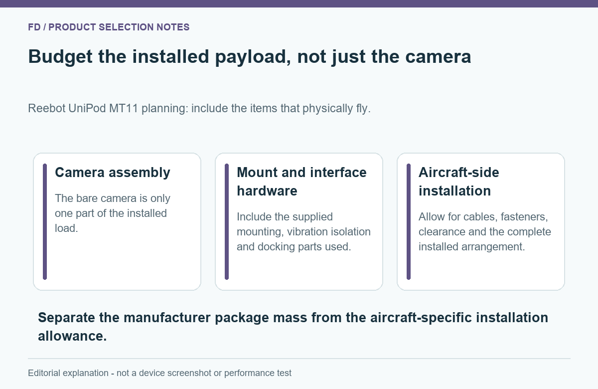
The official specifications give two package descriptions because a camera can be considered in different installation arrangements. They are not two conflicting estimates of the same complete object. The 128.5 g nominal difference is the difference between those stated assembly totals; it should not be advertised as a separately weighed dock or board component unless the manufacturer supplies that breakdown.
The lighter figure can help an integrator evaluate a more direct installation, but it is not a shortcut to a lighter finished aircraft. A custom bracket, isolation arrangement or interface solution might replace some of the omitted hardware. Its real mass belongs in the comparison. Compare complete proposed installations rather than one complete package against one bare camera.
The ±5 g figure also has a defined scope: it is attached to the manufacturer-listed product assembly. It is not a tolerance for the entire aircraft installation, and it does not cover unmeasured accessory parts. When close to an allowable limit, the final assembly should be weighed in its actual configuration rather than treating nominal figures as a completed engineering check.
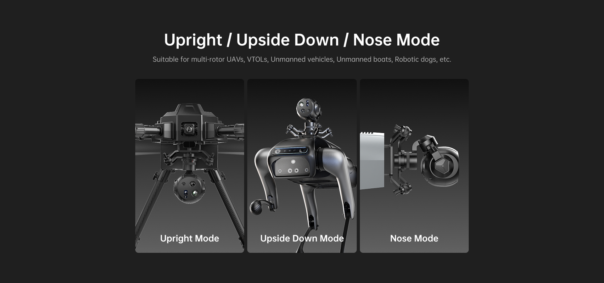
A payload can fit within a mass allowance and still be unsuitable for the available space. The camera needs adequate clearance through its intended movement, the cables need a sensible route, and the ground clearance must suit the aircraft. The mounting position also changes how the mass is distributed. A permitted overall weight does not establish an acceptable mounting load or aircraft balance.
The current MT11 material illustrates different mounting orientations. Those illustrations show configuration possibilities; they do not certify that a particular bracket or aircraft can use every orientation. Ask for the drawing of the proposed delivered assembly, including the parts that connect it to your aircraft. A generic product silhouette is insufficient when clearance is tight.
This article does not quote a single set of MT11 dimensions because the public size labels for different mounting configurations are inconsistent. That omission is more useful than silently choosing the smallest figure. Resolve the actual assembly dimensions from a matching drawing before committing to a bracket, while keeping the stated mass calculation as a separate check.
The interface dock is not just packaging weight. It belongs to a particular integration arrangement and should be selected for the connections the installation needs. MT11 lists Ethernet video and control inputs including S.Bus, UART and Ethernet. A connector list does not mean every aircraft uses every interface or that all required cables arrive in a camera-only offer.
A useful package description distinguishes the camera, its board and dock, the aircraft bracket, and the aircraft-side connections. That makes it easier to understand two quotations that otherwise look like prices for the same model. Removing the dock to compare the lowest weight can change the work needed elsewhere in the installation.
Quick-release names also need care. The MT11 manual describes a directional compatibility difference with older SIYI mounting hardware; it does not establish universal interchangeability. Do not assume an existing bracket or older quick-release assembly is suitable merely because another camera from a related ecosystem used it. Check the exact mating parts rather than treating “quick release” as a standard connector.
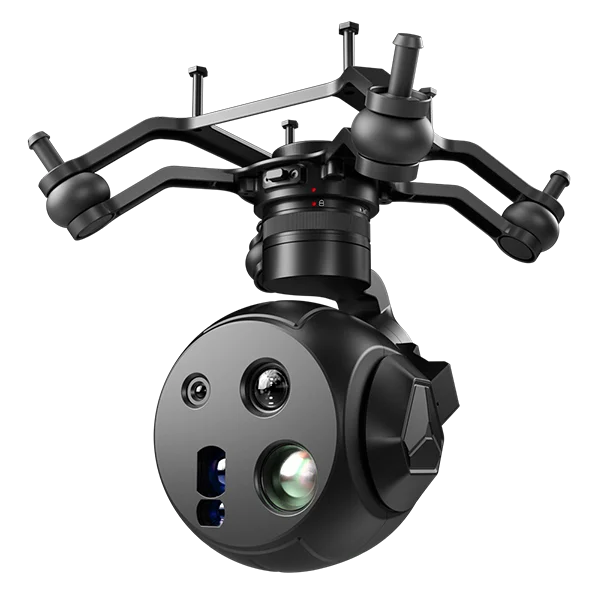
The supplied board's anti-vibration description explains its intended role. It does not prove the footage will be equally stable on every airframe. Aircraft vibration, mounting stiffness, cable forces and installation geometry can all affect the delivered image. A visible photograph of dampers is not a measurement of isolation performance.
For a purchase comparison, request a representative original clip made with a stated mounting arrangement. Examine the kind of detail the customer needs to review. If a sample uses a different bracket, aircraft or camera orientation, it can still illustrate the camera's output, but it does not establish the performance of the proposed installation.
Choose the mounting package for its documented fit and the intended integration rather than for an assumed quality ranking. The bare configuration is not automatically a poor choice, and the heavier assembly is not automatically an improvement. An appropriate installation is the one that meets the mechanical, electrical and image requirements together.
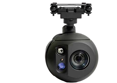
Weight is a constraint, not the entire reason to buy a camera. MT11 combines visible wide-angle and zoom channels with native 640 × 512 thermal imaging through an 18 mm lens. Its 11x optical zoom and local visible 4K30 recording can be useful when a civil inspection needs context, visible detail and thermal comparison in one payload.
Compare that benefit with the actual job. If only a general visible record is required, a simpler visible-only payload may deserve consideration. If related visible and thermal observations are important, the additional channels have a clearer purpose. Neither decision should be made by the lowest bare weight alone.
Keep the recording labels accurate while comparing. MT11's 8000 × 6000 setting describes still photographs, not 8K video. Its native thermal resolution is not the same as an AI-enlarged image. A lighter installation cannot compensate for buying the wrong imaging capability, and an impressive resolution headline cannot compensate for a package that does not fit.
Send the available aircraft payload allowance, a mounting drawing or clear photographs of the attachment area, the required orientation and the expected video connection. State whether the aircraft already has suitable power hardware and whether an existing quick-release component is intended for reuse. Unknown values can remain explicit questions rather than guessed numbers.
Ask the supplier to identify the included board, dock, bracket and cables, then request the complete proposed mass and its basis. That produces a more useful comparison than two prices with differently scoped weight claims. For the model's current imaging and mounting options, review the Reebot UniPod MT11 package available from FD.
No. It is the nominal difference between the two published assembly totals. Without a separate component breakdown, do not assign the entire difference to the dock or to the anti-vibration board.
The figures alone are insufficient. Aircraft efficiency, battery condition, other payloads and operating conditions influence flight time. No fixed endurance reduction is established by this article.
That cannot be concluded from its mass or name. Stabilized image quality depends on the complete installation and conditions. A comparison needs representative footage rather than a claim based on the included board.
Only after its actual mating geometry and approved configuration are checked. Similar appearance and a shared product ecosystem do not establish that the older assembly fits MT11.
No. It totals the listed example components and illustrates the product's published weight tolerance. Accessory uncertainty and any required design margin must be determined for the real aircraft and installation.
Source basis: Reebot UniPod MT11 official specifications, User Manual v2.0 and the FD model listing, checked 20 October 2026. Extra component weights and the 650 g allowance are labelled calculation examples. No aircraft-fit, endurance or vibration test is claimed.

 Tel: +86-13959965075
 Email: info@fpvdroneskit.com
 MP/WhatsApp: +86-13959965075
 Manufacturer Address:Quanzhou Valley Nanan Science and Technology Innovation Center, No. 89 Shijing Avenue, Shijing Town, Nanan City, Fujian Province