| Price | On request |
|---|---|
| Model | DIY10G207-E |
| Visible camera | 1/2.8-inch 2 MP CMOS; nominal 10× optical zoom |
| Thermal imager | 256 × 192; fixed 7 mm lens; 12 µm; 8–14 µm |
| Stabilization | Three-axis gimbal; gyroscope electronic stabilization listed |
| Video output | RTSP network IP; 1080p30 mode |
| Storage | Local TF photos and video |
| Power input | 12–26.2 V DC; Dynamic 6.5 W |
| Thermal lens | 7 mm |
| Control interfaces | IP / UART / S.Bus |
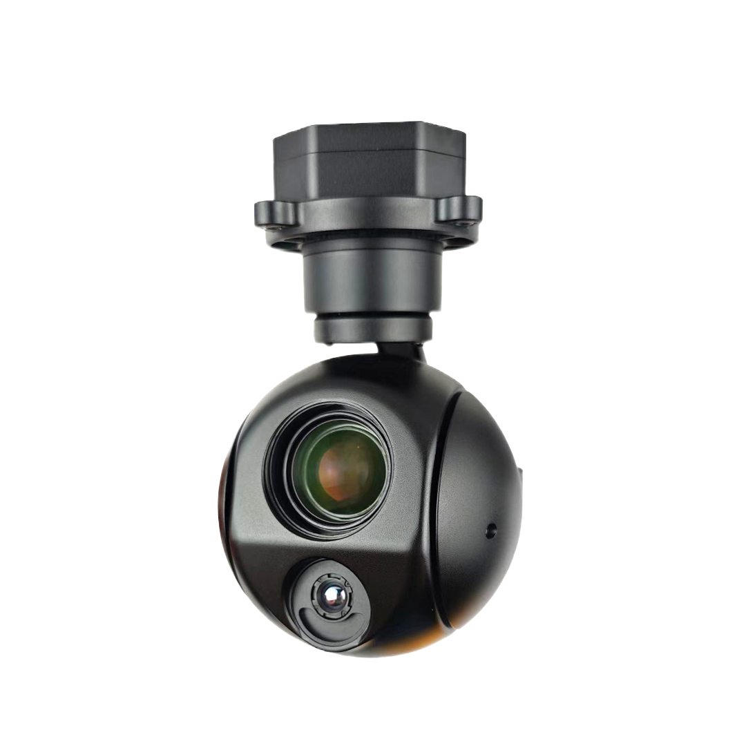
DIY10G207-E combines a three-axis payload with two inspection views: 10× optical zoom for visible detail and a 256 × 192 detector for thermal imaging. Civil UAV teams can use the visible channel to examine a particular part of the scene while keeping a thermal view available for the same project.
The visible lens lets an operator move from an overview to a closer view of roof fittings, structural joints or equipment housings. The 7 mm thermal camera adds heat-pattern observation, while RTSP network video and TF-card storage support viewing during the flight and reviewing the saved material afterwards.
The useful selection question is the size of the feature in the image at the planned working distance. This model's 10× optical zoom changes the visible camera's focal length; its 256 × 192 infrared detector has its own fixed 7 mm lens. Choose the visible zoom around the inspection detail, then evaluate the thermal view around the area you need to cover.
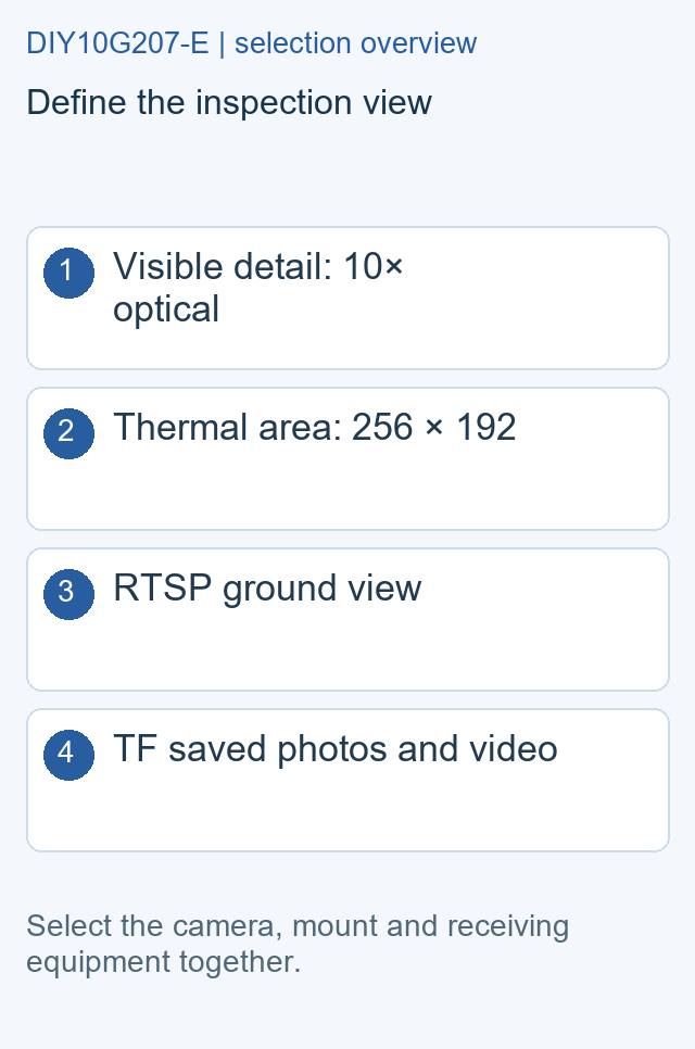
The detailed product table lists RTSP IP video with a 1080p30 mode and local TF photos and video. IP, UART and S.Bus provide control options for the camera and gimbal; PWM is an optional control configuration. A receiving system that supports the required network video format gives the operator a practical way to view the image and manage camera functions.
| Item | DIY10G207-E configuration |
|---|---|
| Visible sensor | 1/2.8-inch, 2 MP wide-dynamic CMOS |
| Visible optics | 10× optical zoom |
| Thermal imager | 256 × 192; 7 mm lens; 12 µm pixels |
| Gimbal | Three-axis; electronic image stabilization listed |
| Video / storage | RTSP IP, 1080p30; local TF photos and video |
| Input / power | 12–26.2 V DC; dynamic 6.5 W |
Describe the fitting, joint or component that the visible camera must show. A sample scene and planned working distance help select a useful zoom setting and framing.
Specify whether the thermal view is for a whole roof section or individual equipment. Match the area of interest to the 7 mm lens rather than choosing by zoom number alone.
Name the ground receiver, control interface and saved files needed by the reviewer. Plan the card, power feed and mounting space before completing the payload kit.
Include your UAV model, installed payload allowance, network receiver and preferred control method. State the visible detail and thermal area to be inspected, plus any temperature-data requirement. Ask for the camera, mounting parts and cable set together so the quotation covers the equipment your installation needs.
No. The 10× optical specification belongs to the visible camera. The thermal channel uses a fixed 7 mm lens and a 256 × 192 detector.
The model combines a three-axis gimbal with a listed gyroscope-based electronic stabilization function. For your selection, request an original video at the zoom setting and scene detail you plan to use.
Describe the surface and viewing area, then say whether the result you need is a thermal image or saved temperature information. That gives the camera configuration and file requirements a clear starting point.
Specification reference: manufacturer DIY10G207-E product data.
| Visible Camera | 1/2.8-inch 2 MP CMOS; nominal 10× optical zoom |
|---|---|
| Thermal Imager | 256 × 192; fixed 7 mm lens; 12 µm; 8–14 µm |
| Stabilization | Three-axis gimbal; gyroscope electronic stabilization listed |
| Video Output | RTSP network IP; 1080p30 mode |
| Storage | Local TF photos and video |
| Control | IP / UART / S.Bus |
| Voltage | 12–26.2 V DC |
| Power | Dynamic 6.5 W |
Review RW10 compatibility by resolving Windows/Ubuntu, 4400/5550mAh and 5.8GHz/1.4GHz records and defining kit deliverables....

Review TAKER H65_8S ESC delivery through firmware state, 3–8S power matching, signal protocol, current sensing and cooling....
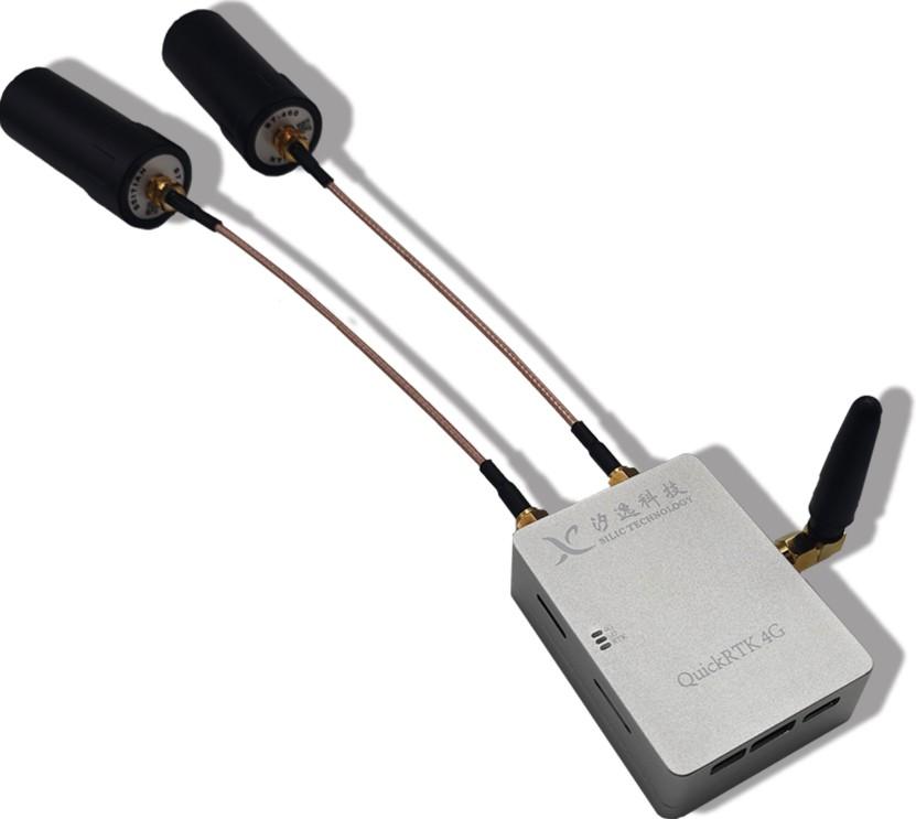
Evaluate G982-4G through receiver and modem identity, antennas, correction transport, timing, raw logs and checkpoint validation....
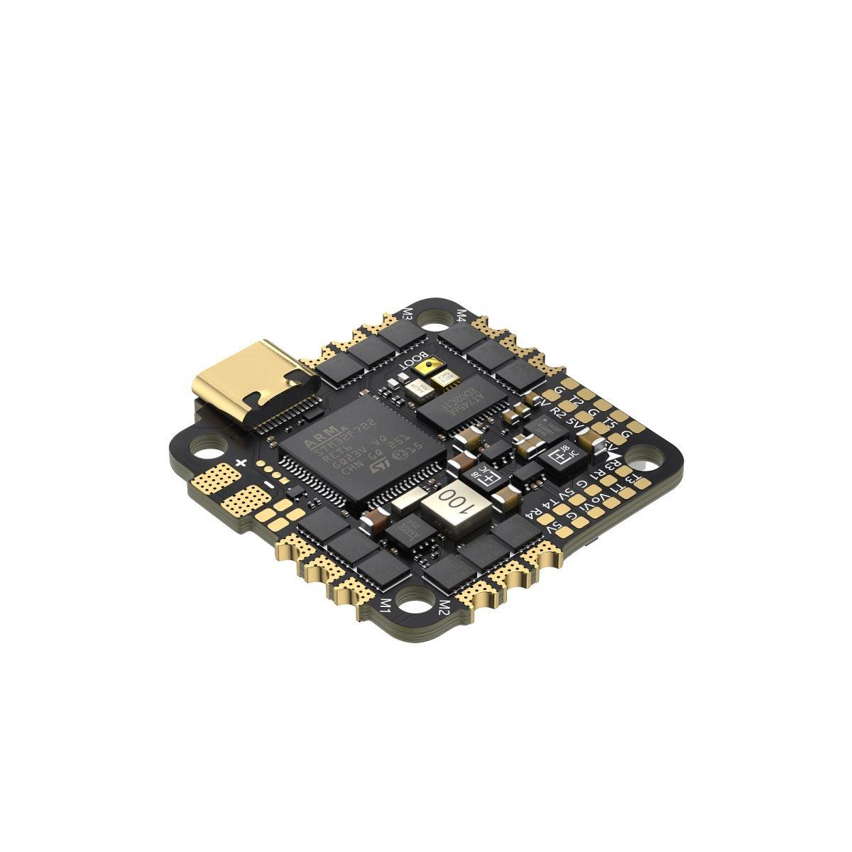
Map TAKER F722 45A AIO compatibility through its five UARTs, six-pin HD port, 5V rail, firmware and propulsion evidence....
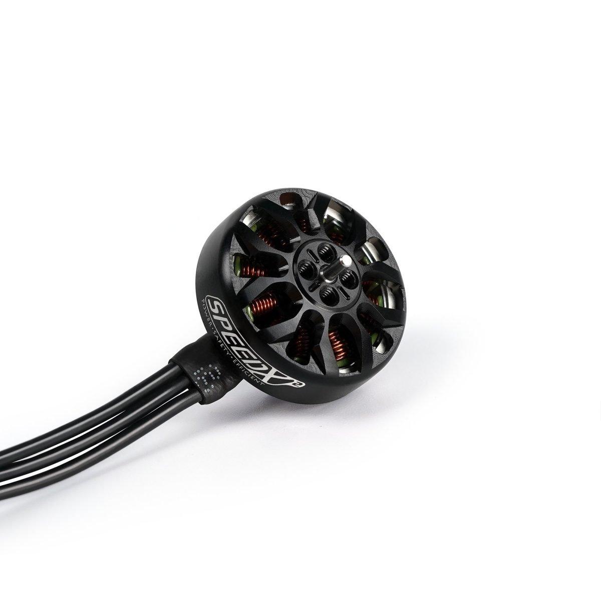
Match the SPEEDX2 1804 3450KV motor by drawing, pusher clearance, battery, propeller, ESC and a winding-specific test row....
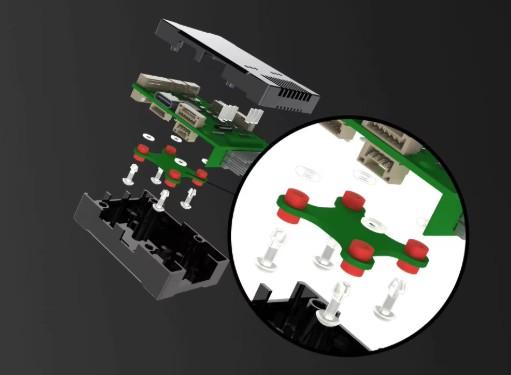
Review S7 Mini compatibility through its STM32H743 board revision, sensor set, port map, rail limits, firmware and recovery file....

 Tel: +86-13959965075
 Email: info@fpvdroneskit.com
 MP/WhatsApp: +86-13959965075
 Manufacturer Address:Quanzhou Valley Nanan Science and Technology Innovation Center, No. 89 Shijing Avenue, Shijing Town, Nanan City, Fujian Province